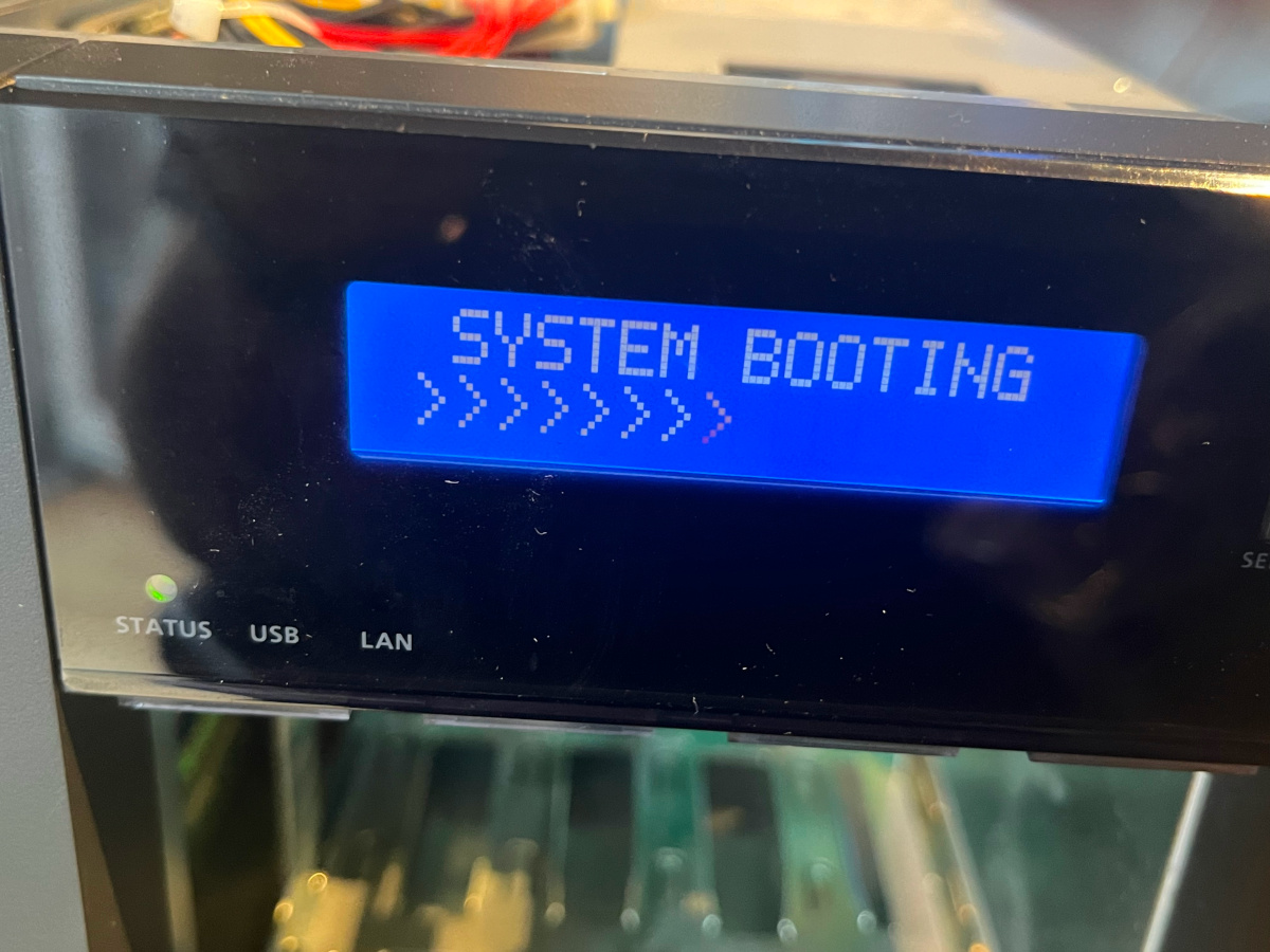
The other day my QNAP TS-453 Pro died suddenly and would not boot any more after firmware upgrade. It showed an endless loop of “SYSTEM BOOTING” along with scrolling >-signs. Fearing the data would be lost I was about to order another unit and transfer the hard disks over.
Following a few posts on the internet revealed that almost any post refers to [1]. This recommends soldering a 100 Ohms resistor to pin 1 of the LPC connector and to GNC via pin 8 or 10. So I went to open the box and locate the LPC connector. This is far easier than expected. It sits right at the edge of the main PCB in the middle between front and rear.
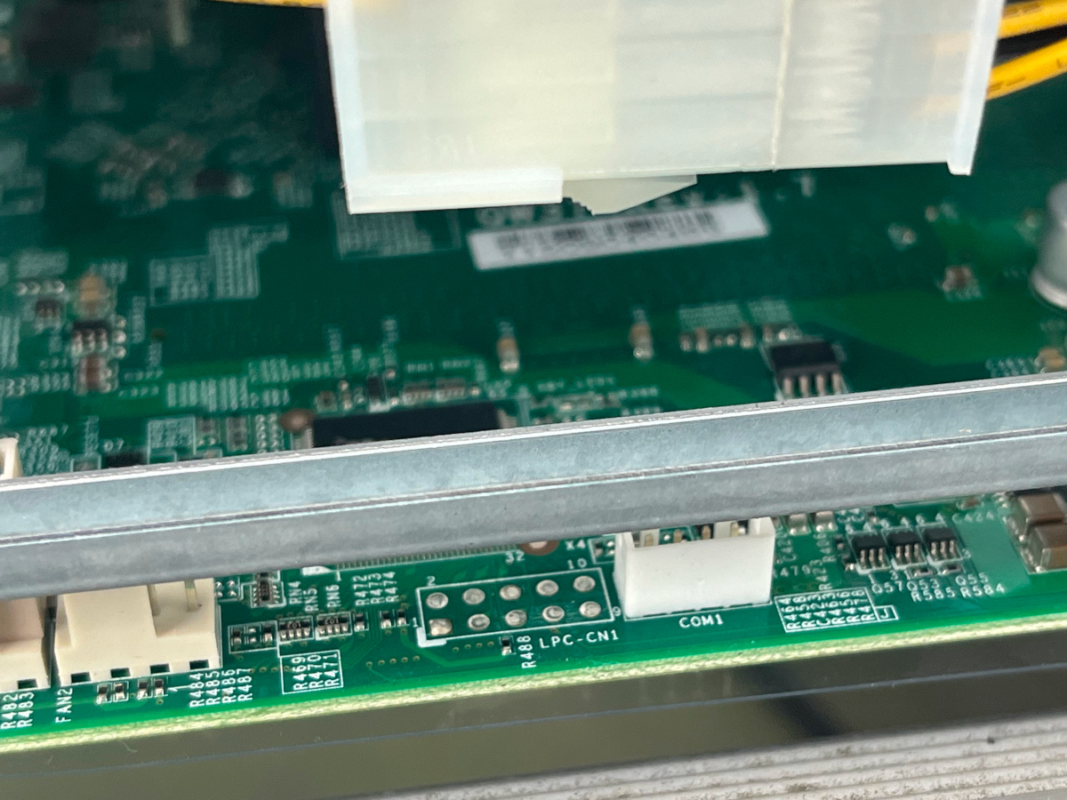
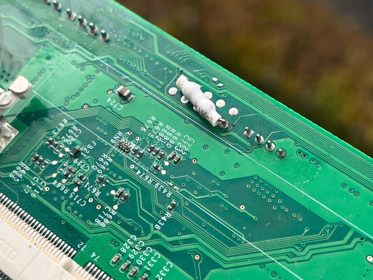
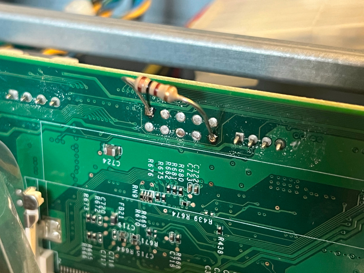
Instead of soldering a resistor to the mounting/top side of the PCB I chose the lazy man’s option to do that at the bottom. The board is shielded by a transparent piece of plastic which can be folded away after removing one mounting screw of the board. A 100 Ohm resistor was soldered to pins 1 and 10 on the bottom side of the PCB. For security reasons it was covered in heat shring tube.
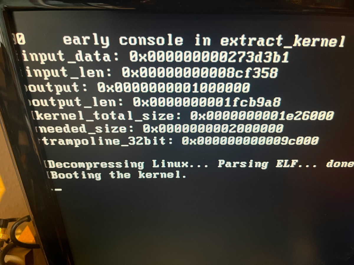
With that modification the box showed the expected boot screen on the HDMI output:
In case you have difficulties locating pin 1 (and 10) on the connector see the picture of my pre-production test installation of the resistor:
Please be aware that this may eventually break your warranty. Use at your own risk. I am not liable in any way for damage to your equipment.
References:
[1] https://forum.qnap.com/viewtopic.php?f=45&t=135089&start=150#p767546