A while ago I wrote about a Homemade Data Cable for Yaesu FT-2D which I built from a sample 11-pin USB connector. I got the special connector for the radio from a European manufacturer who apparently only sells it in MOQ of 1000 pieces or more. On a thread on Twitter [1] someone suggested to slaugther a clone cable to see if one could make two programming cables out of that. The benefit would be that the cloning cable only costs ~ 25 € while the original SCU-19 is around 90 € and you could even make two by cutting it in half. So here we go. Challenge accepted.
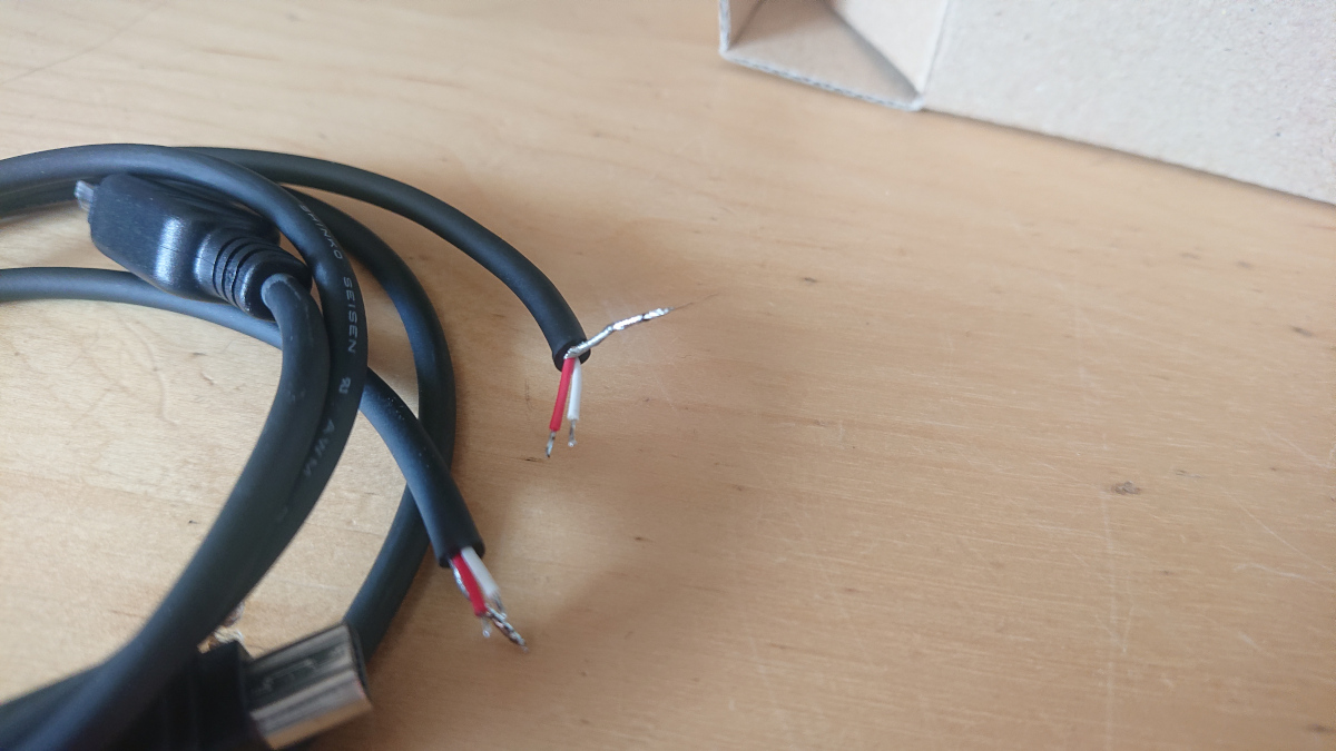
First thing was getting a CT-168 cloning cable and see whats insinde. After cutting in the middle it shows that there is only 2 wires (red and white) and screen. So that obviously is just a crossover serial cable without hardware handshakes. The section is depicted in the following (bad) macro photo of the plug.
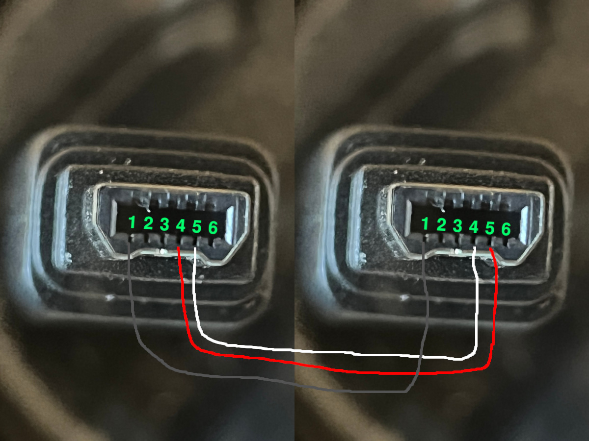
So this seems like a simple nullmodem cable for Yaesu radios. From my previous analysis I knew that the original SCU-19 contains a pl2303 USB serial adapter along with a level shifter. So I used half of the CT-168 cable with a Logilink AU0002E USB serial adapter based on a pl2303 chip. It obviously has to be a USB serial adapter with level shifters to RS-232 levels. So a plan pl2303 will not work. Please note that I did not test other USB serial chips (FT232 / CH340).
So one option here is to just get a pl2303 USB serial adapter and solder a D-Sub 9 connector to the open end of the half CT-168 cable. The pinout would be as follows.
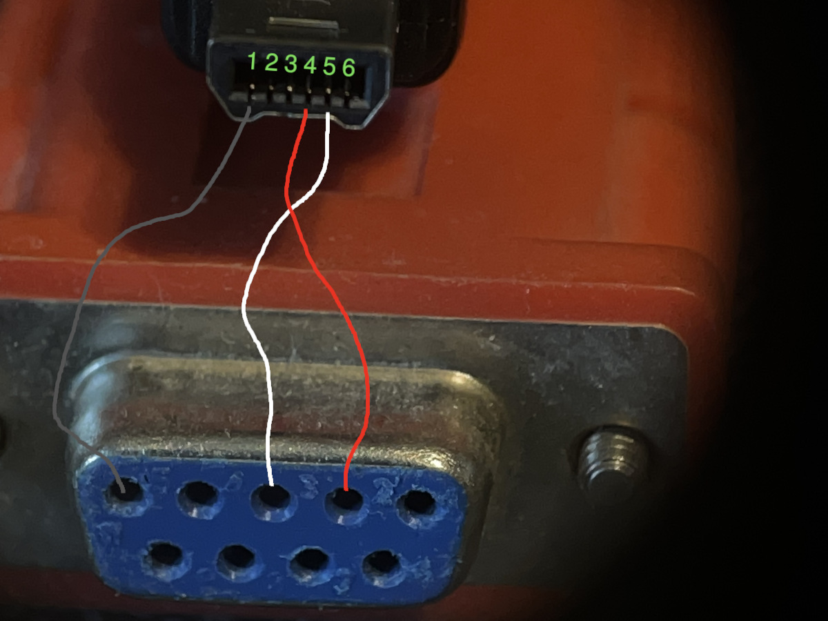
According to my (arbitrary) pin numbering on the FT-2D connector side this would be.
RS-232      FT-2D
  2 -- RX --- 4
  3 -- TX --- 5
  5 -- GND -- 1
Beware that the colors of the wire are differing (red and white interchanged) depending on which half of the CT-168 cable you used ;-)
I did not like the rather large (and useless) RS-232 connector in the middle of the cable. So I went for implementing the PCB into a small USB connector case. The Logilink USB serial adapter got its case cut off and the D-Sub connector desoldered. Also the PCB had to be shortened a little in order to fit into a (rather small) Arduino USB serial adapter case. Therefore I had to solder the 2 data wires directly to the MAX211 level shifter (on the bottom side of the PCB in the following picture).
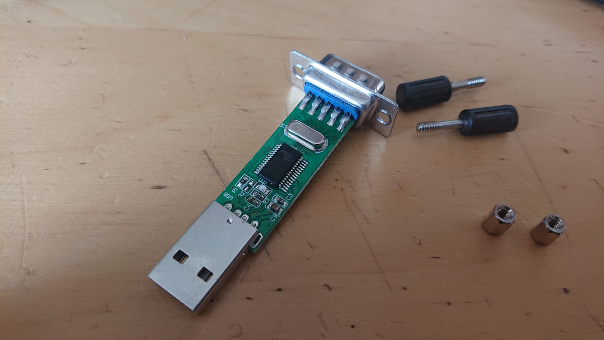
As the pads for the RS-232 connector got cut off due to limited space in the case the wires of the cable had to be soldered to the MAX211 directly. So here is the pinout of the chip for reference:
FT-2D       MAX211
  1 -- GND -- 10
  4 --- RX -- 18
  5 --- TX --- 3
This may vary for other adapters depending on the assignment of RS-232 in- and ouputs between pl2303 and MAX211 or other level shifters. Apparrently there is no picture from the integration into the case. But here is what the final result looks like.
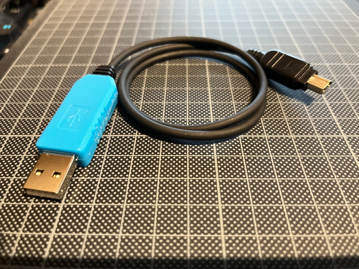
The homemade adapter just reads and writes my FT-2D just fine. So no need to buy horribly expensive cables nor pulling and writing SD cards any more. See [2]
Update
One still open question was whether the ADMS-8 programming software for FT-2D explicitely checks for pl2303 USB serial devices or if it would works with any USB serial adapter. In order to test this I wired up the half CT-168 to a D-Sub 9 connector and connected it via a Digitus DA-70156 to the windows machine. After selecting the corresponding COM port it would read and write the FT-2D just fine. So you can use any USB serial adapter ant not only pl2303 based ones. Beware that you need RS-232 levels meaning a level shifter (e.g. MAX211) is required. So simple USB serial boards with only FT232 on it will not work.
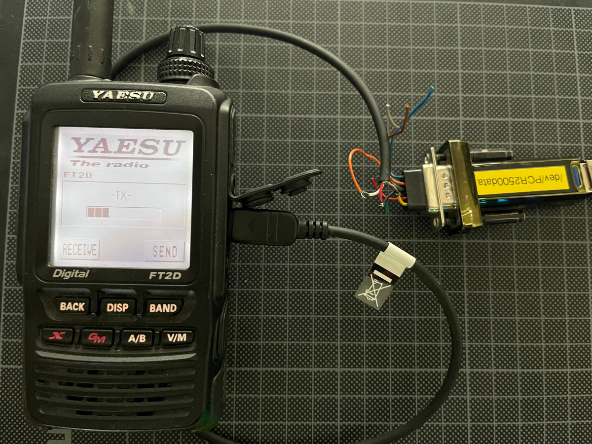
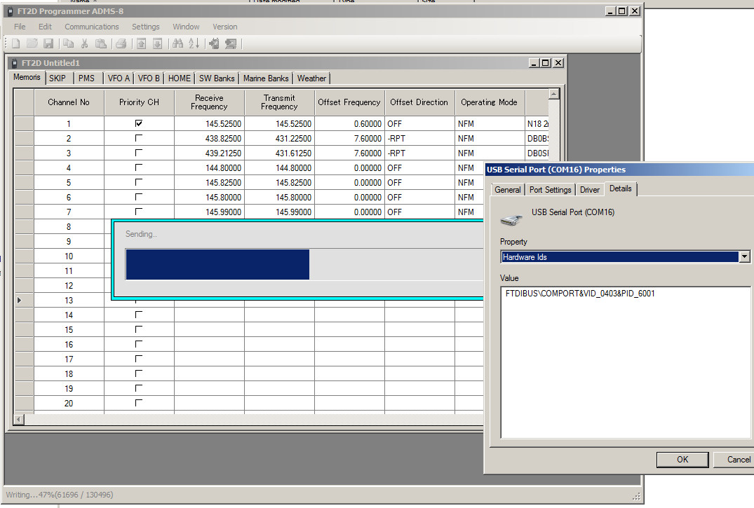
Please be aware that this may eventually break your rig. Use at your own risk. I am not liable in any way for damage to your equipment.
References:
[1] https://twitter.com/darc_h33/status/1480873413245816834?s=20&t=NXkcI5FlW6BufVTYpL2JEw [2] https://twitter.com/flo0/status/1502033992924680200?s=20&t=owDbm0jwDaFOlFMGoY_7EQ