Recently received questions about (full duplex) FT8 operations on QO-100 from various stations. So this aims to be a complete how-to documentation of my setup. Hardware is an ICOM IC-9700 with MKU UP 2424 B up converter for 144 MHz to 2.400 MHz conversion and Kuhne MKU LNC 10 QO-100 converter on the downlink converting 10 GHz to 433 MHz. Your mileage may vary. As software I am using WSJT-X improved by DG2YCB (see [1]). This is a version that includes some features which are not merged to the official WSJT-X branch (yet). The aim is to operate FT8 via satellite full duplex.
Radio Settings
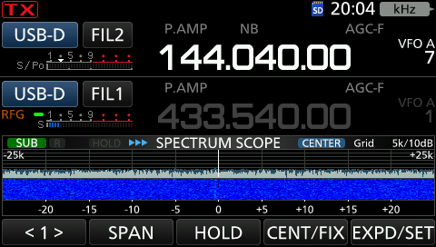
All noise cancelling mechanism like NR or NB as well as notch filters are disabled. The filter of the RX band (upper VFO) is set to maximum bandwith (i.e. 3.6 kHz). RX mode is set to USB. The transmitting band is the bottom VFO. The mode is set to USB-D (data) and filter is be set to FIL2 (i.e. 1.2 kHz in my case).
The main screen during operation looks as follows:
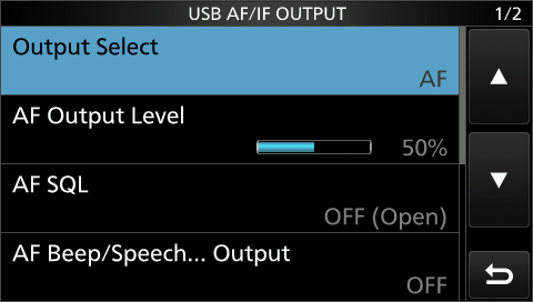
The USB port is configured for output of AF and AF Output level is at 50% (default).
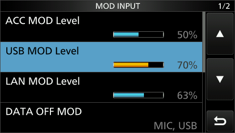
The USB MOD Level is set to 70% and DATA MOD is set to “USB” (one item further down the menu and not shown on the screenshot).
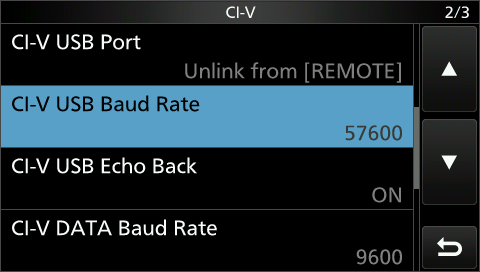
The CI-V settings are at default except the baud rate for the USB CI-V interface which is set to 57.600 baud.
This should be all relevant settings on the radio.
Software Settings
By default it seems that the input sound device for the IC-9700 is set to mono. To enable both channels set the format to “2 channels, 16 bit, 44100 Hz (CD Quality)” in the advanced sound settings. This is required because in full duplex mode the RX audio is send via both channels (i.e. each VFO on a separate channel). Otherwise you will only have the audio of the TX VFO on input. The device name usually is “USB Audio CODEC”.
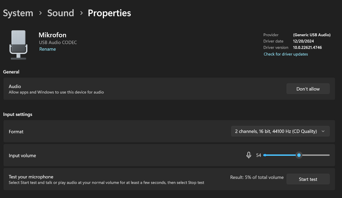
This setting has to be adjusted before WSJT-X improved is started.
WSJT-X Configuration
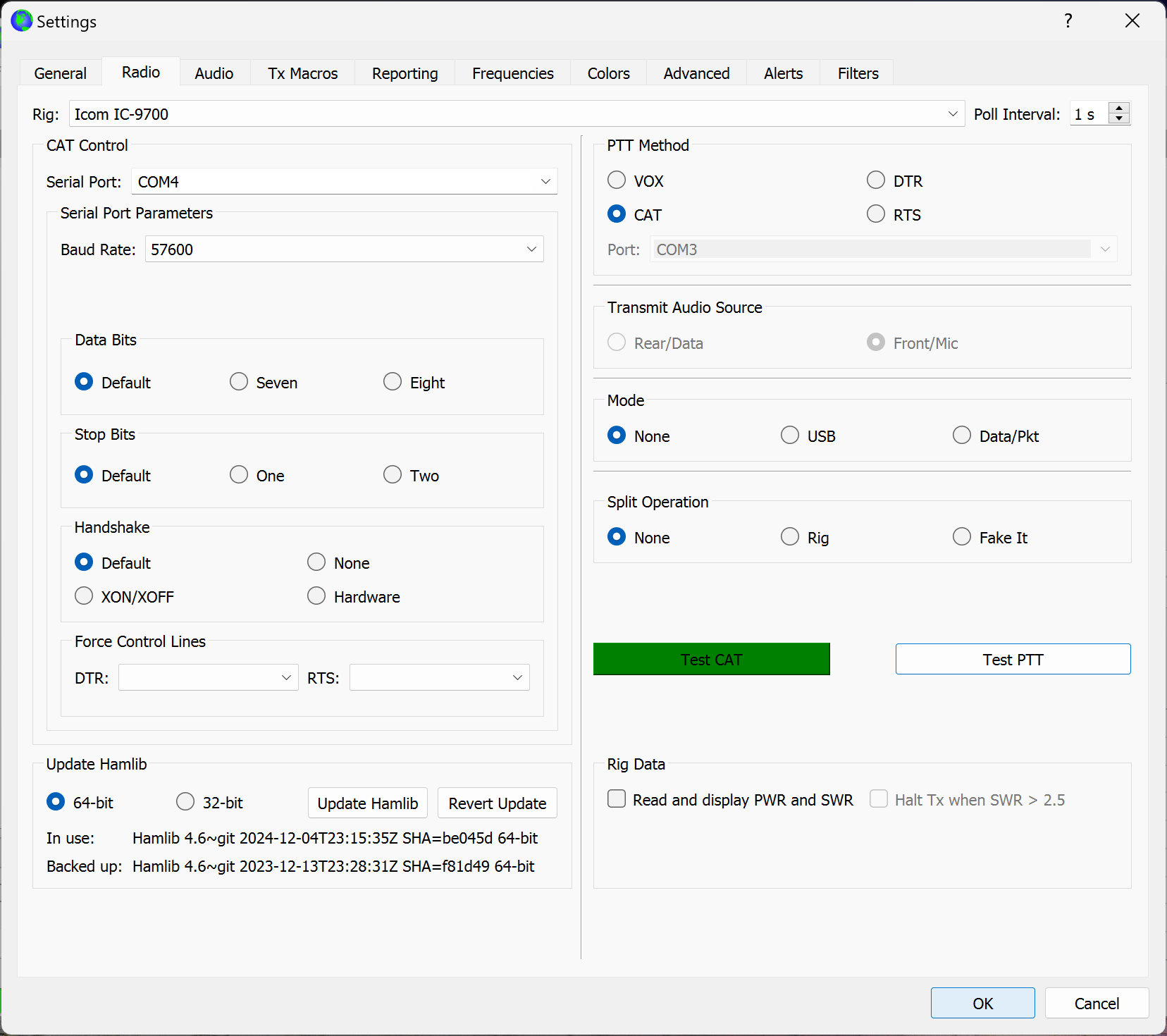
For controlling the radio CAT control is enabled in WSJT-X improved. This needs configuration of the correct serial port. My settings are baud rate at 57600 data and stop bits set to default. This can be tested with the “Test CAT” button which turns green if CAT control works. PTT is also controlled via CAT so no need for an extra serial port. Mode and Split Operation are set to “None”. Again test can be performed using the “Test PTT” button which should trigger the PTT on the radio.
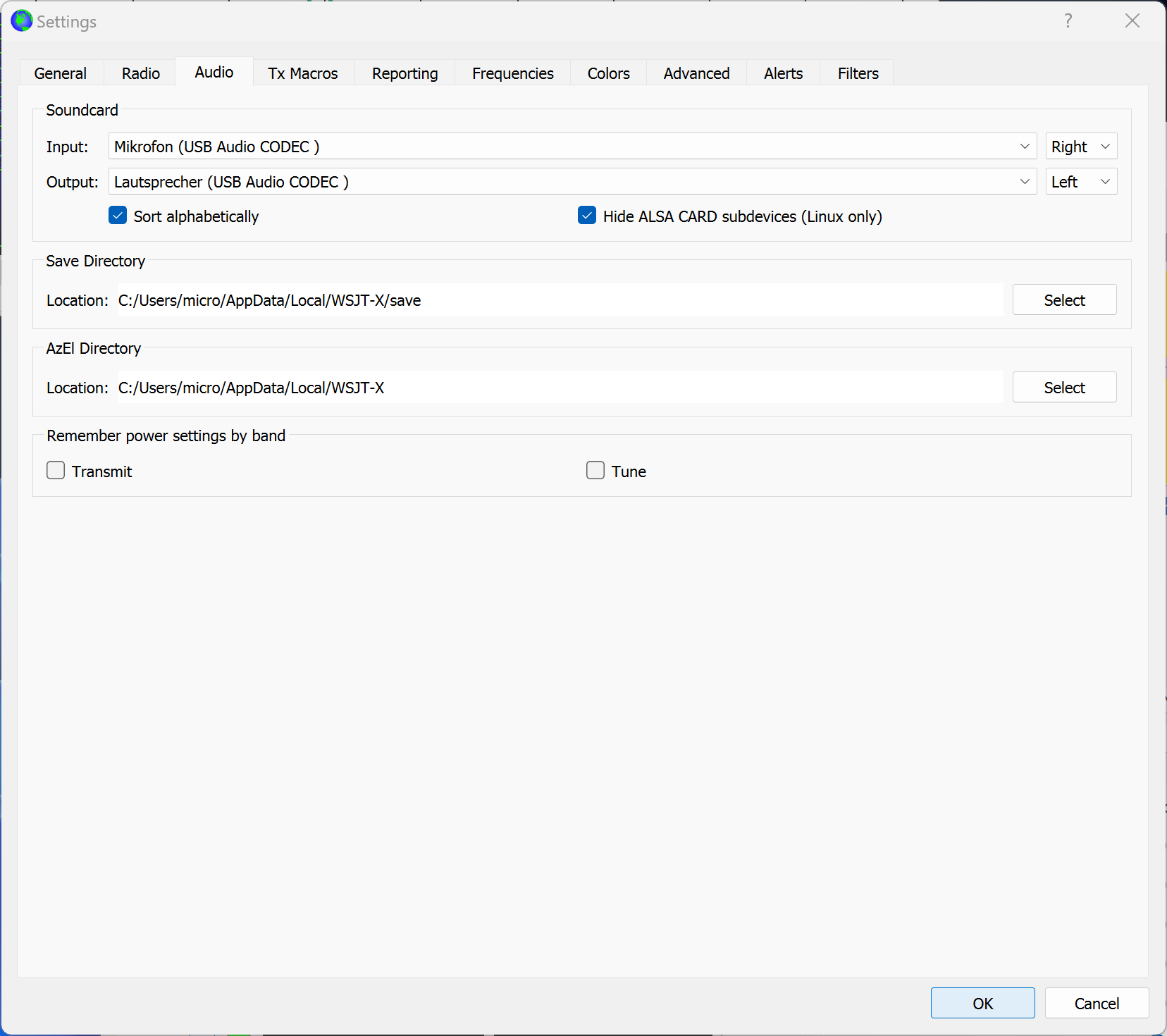
If you operate both bands of the IC-9700 simultaneously as we assume here you need to adjust the audio settings. After setting the input source to 2 channels (see above) you should select the correct channels in the audio settings. The TX VFO at the top display of the IC-9700 usually is the left channel. The bottom and receiving band is transferred via the right audio channel. So you have to set the input to right and the output to left (or both) channels.
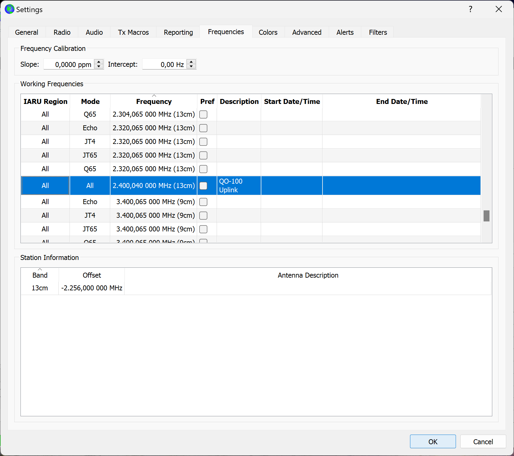
For logging purposes and to reduce the need to manually correct the log afterwards I configure an offset for 13cm (uplink band). This way the TX freqency (and band) is logged as 2.4 GHz and 13cm. The LO in my upconverter is set to 2.256 MHz. So an offset is added which is calculated as 2.400,040 MHz - 2.256,000 MHz = 144.040 MHz. So the CAT frequency of 144.040 MHz is added to the LO and results in 2.400,040 MHz. Beware the minus sign within the offset. The offset can be added by right-click in the lower table.
Also a working frequency of 2.400,040 000 MHz is added to the working frequency table. IARU Region and Mode are set to “All”. A description may be added as well. Now if you later select this frequency in the main window the radio is set to the intermedia frequency on 2m. The big issue here is that the built-in SAT mode cannot be used because the CAT control via internal hamlib cannot control the IC-9700 correclty if SAT mode is enabled (see [3]). Therefore you just have to enable both bands / VFOs but leave the satellite mode off.
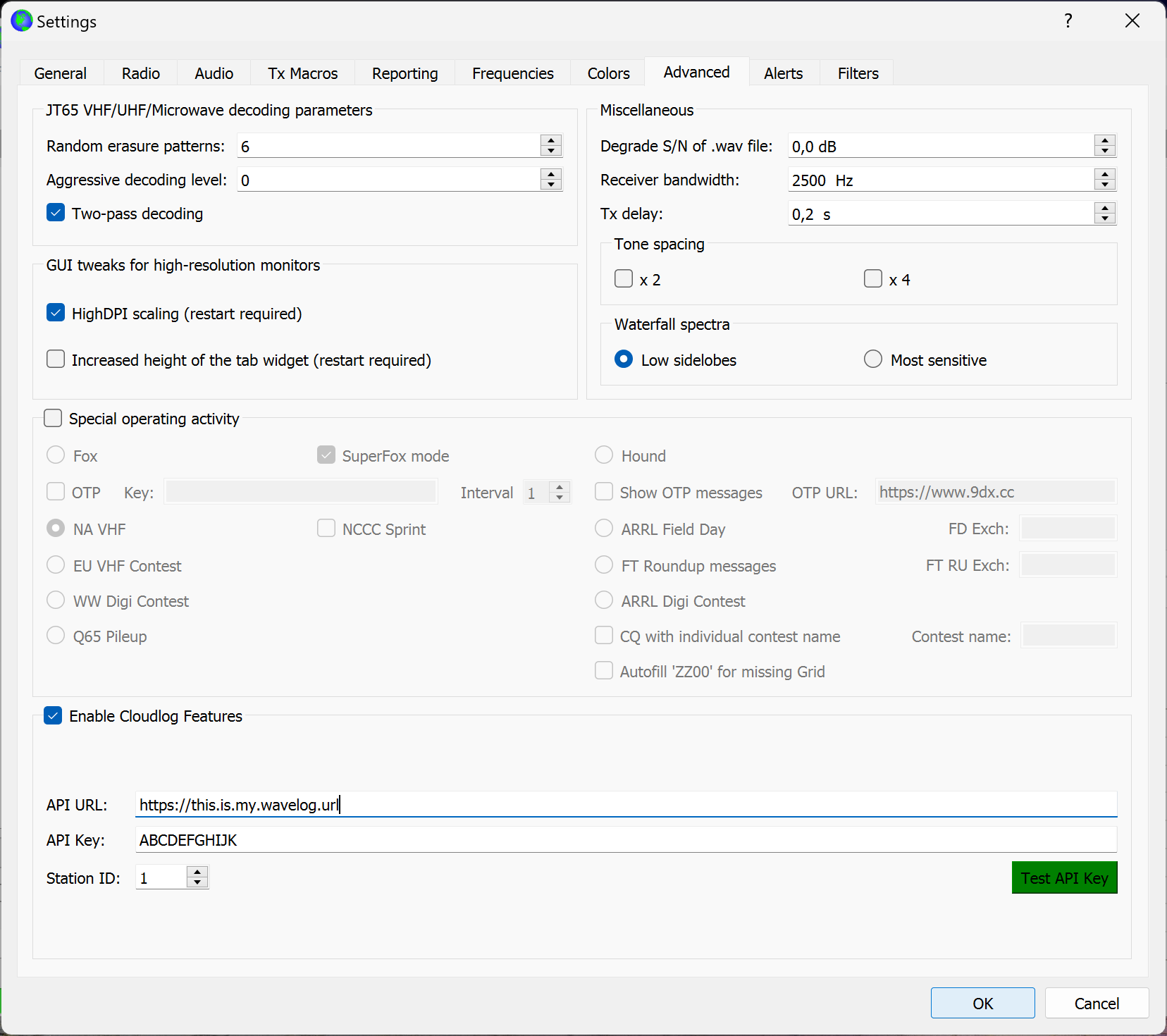
If Wavelog or Cloudlog are used as logbook there is an option to configure the API access on the “Advanced” configuration tab. The station ID has to be looked up in the station location settings within Wavelog. Configuring the URL and API should result in the test button turning green if all is working correctly. This is totally optional and not necessarily needed for FT8 operation.
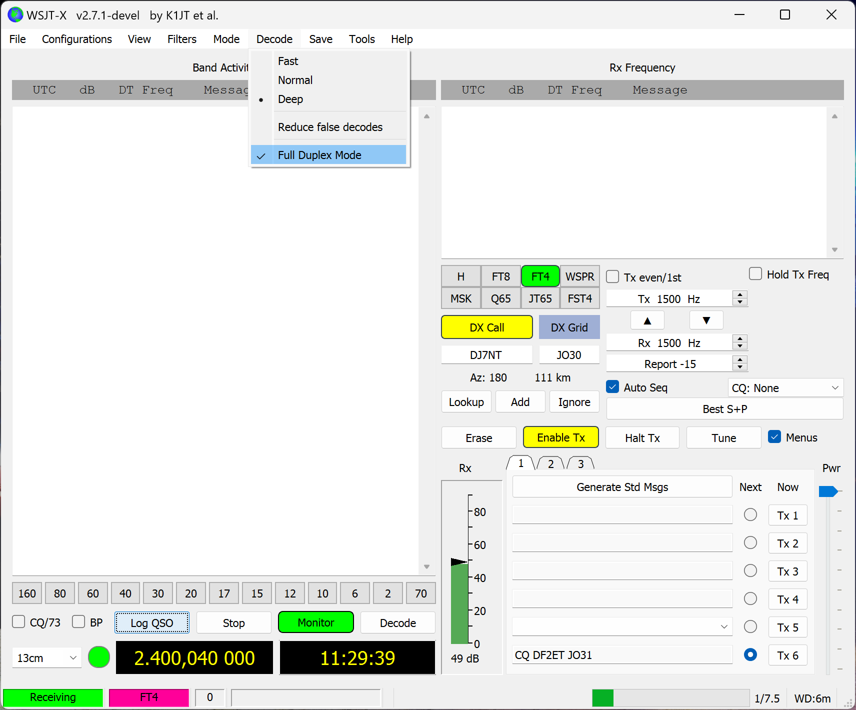
It is helpful to enable the full duplex mode while working satellites. This is a recent addition to WSJT-X improved and can be activated in the main menu of the main window under “Decode”. With this activated you should be able to decode your own transmissions received via the loop on the satellite. If you use this newer full-duplex function in WSJT-X improved, you will avoid having to use two instances side by side as before.
Operating
If all is configured as above you should be able to operate FT8 almost as normal. A few notes:
TX power can be controlled by adjusting the audio level with the slider on the bottom right. This allows up to -45 dB (!) reduction of the TX signal. Especially if operating full duplex you can directly see the SNR your own signal is decoded with. This may be problematic if the up converter / PA is HF vox operated. Then audio level might be too low and the converter will not switch to TX. So adjust this slider very carefully. Also watch your RX path carefully. the biggest difference between a satellite and HF is: The satellite acts like a repeater. So if you are able to hear your own signal others will hear it too.
Operating full duplex means WSJT-X improved also decodes signals in the TX timeslot. This enables you to see and decode your own signal as well as all other signals within the RX filter. Your own transmissions are shown in yellow in the right window part but also received and decoded in the RX window on the left. There your own transmissions are also shown in yellow.
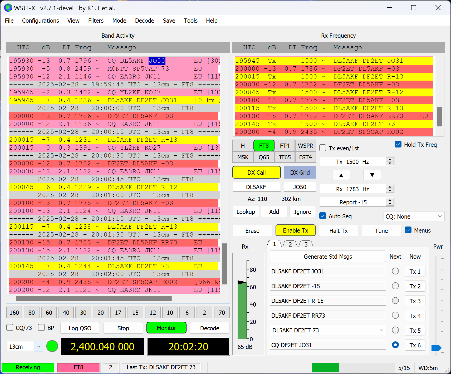
During this screenshot I was transmitting in the odd timeslot maeaning seconds 15 and 45. In the top part you can see YL2KF also transmitting in the same timeslot. Also there is most probably a little shift between your nominal TX frequency and the frequency you receive your own signal on.
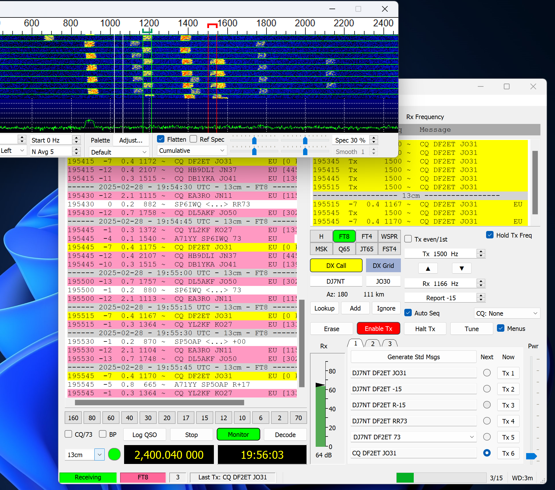
In the picture above the offset is around 370 Hz. TX frequency is set to 1500 Hz (see the red marker in the spectrum view) and the own loop is received back on 1170 Hz (see green marker). Depending on your and your QSOs partners filter width and overall frequency offset it might be recommended to adjust the radio TX frequency (to “guess” if your QSO partner listenes further down or up the frequency).
Logging
After completing a QSO you can add the satellite specific data to the log which is reflected to the ADIF file as well. The propagation mode “Satellite” can be selected in the drop down menu. The satellite names are derived from a text file that contains the satellite data. The file is called sat.dat and is located in C:\WSJT\wsjtx\share\wsjtx in my case. The path may be different on other systems. A list of satellites automatically derived from the Logbook of The World config file and covnerted to the needed format can be found on [2].
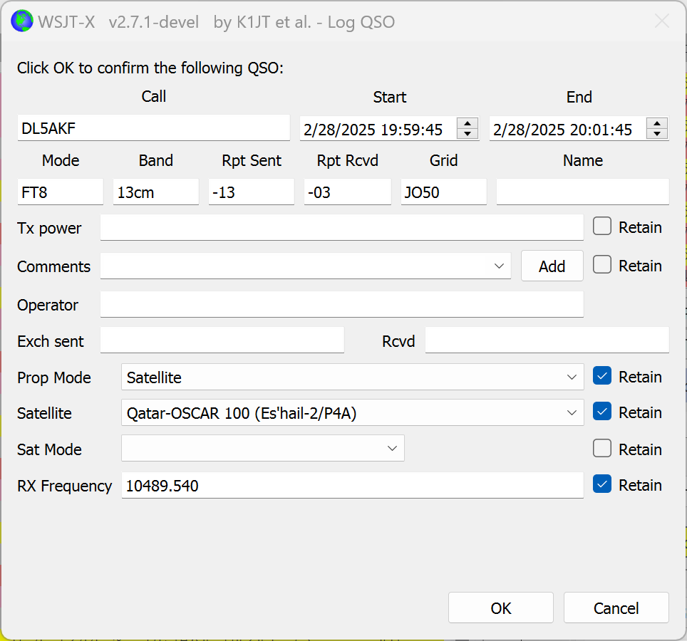
If all is set correctly (and retained for the following QSOs) the QSO is correctly transferred to the ADIF file and includes propagation mode, satellite name as well as TX and RX frequencies. All relevant fields for Logbook of the world are filled and the ADIF could directly be signed and uploaded to LoTW. The resulting ADIF code from the QSO above is:
<call:6>DL5AKF <gridsquare:4>JO50 <mode:3>FT8 <rst_sent:3>-13 <rst_rcvd:3>-03 <qso_date:8>20250228 <time_on:6>195945 <qso_date_off:8>20250228 <time_off:6>200145 <band:4>13cm <freq:11>2400.041500 <station_callsign:5>DF2ET <my_gridsquare:4>JO31 <prop_mode:3>SAT <sat_name:6>QO-100 <freq_rx:9>10489.540 <eor>Please note that the RX frequency is not CAT-controlled due to the hamlib issues mentioned above. Instead it is simply written as specified in the “RX Frequency” field in the log QSO popup. Therefore it cannot include the signal offset within the RX filter as it is done on the RX frequency side. But still this is sufficient to derive the RX band for LoTW and others.
References:
[1] https://sourceforge.net/projects/wsjt-x-improved/files/
[2] https://www.df2et.de/cqrlog/sat.dat
[3] https://www.florian-wolters.de/posts/ic9700-wsjtx-satellite/