This is my notebook showing a teardown of a Tigerbox for repair. In this case the USB-C connector was broken and therefore the box could not charge the battery anymore. The manual says the box should only be repair by qualified personnel. So here we go :)
The USB-C connector sits on a small PCB at the bottom of the box. First you have to remove the rubber pad that is glued to the bottom plate. This reveals 5 screws to remove.
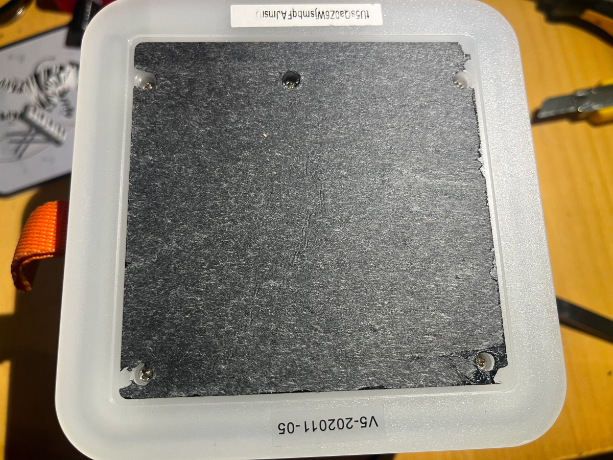
Removing the screws, the cover and a small white piece of reflective material reveals a small PCB which contains the LEDs lighting the bottom part of the box. The small two-pin connector has to be removed.
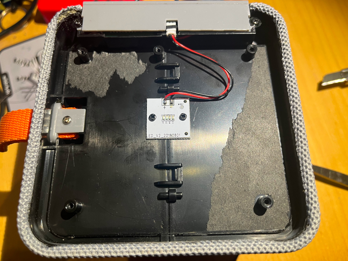
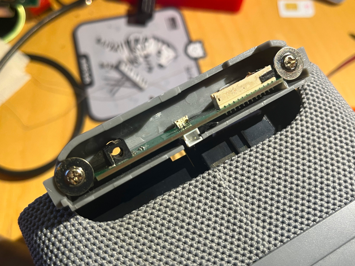
As well for the two small black screws and the grey (your color may vary) plastic piece holding the PCB with USB-C and headphone connectors can be lifted. Be careful here as a 12-pin cable is still connected to this PCB (connecting the main board).
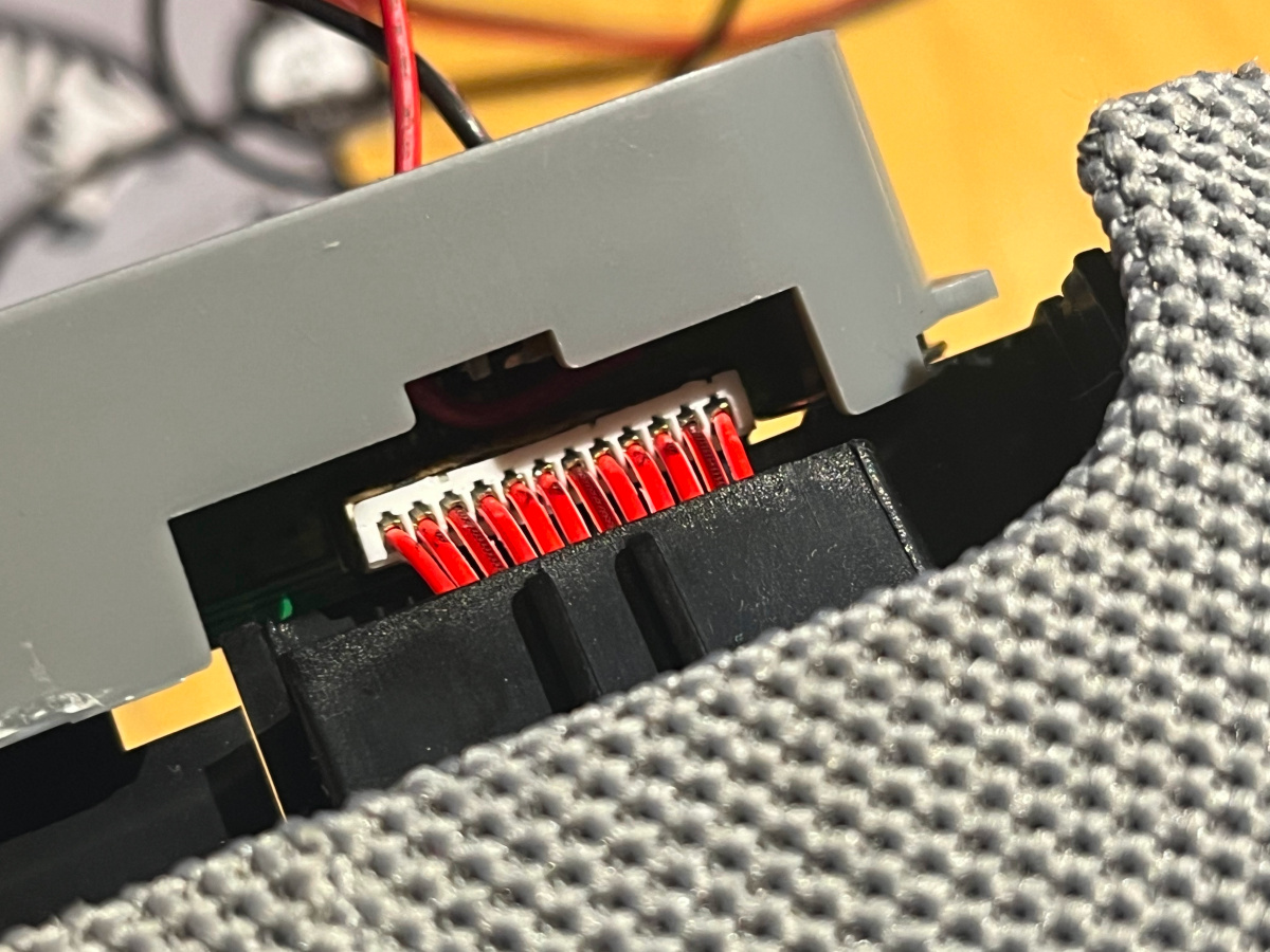
If this is disconnected the bottom part can be separated and repaired or replaced.
# Changing the battery
After disassembling a second box to remove a faulty battery this just documented the disassembly of the top part of the box. The top cover holding the display can be lifted carefully using a flat screwdriver. Be carful to only lift like 5mm otherwise some cables will be ripped of (been there done that). Compare [2].
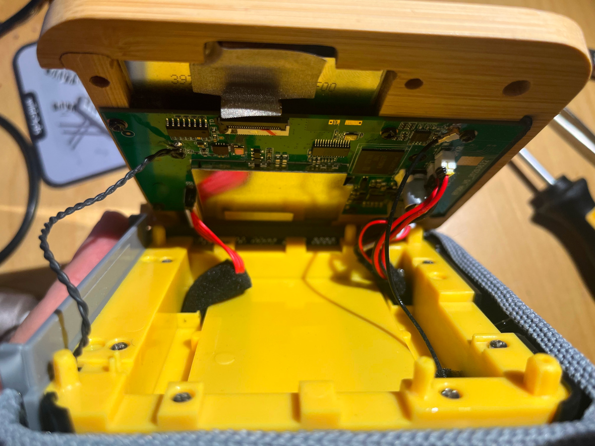
On older versions of the box the battery is located und the cover and fastened with a yellow frame that can be remove by two screws. Those older version use a 2-pin battery cable (red/black). See also [1]. In this case the battery has a 3-pin connector (red/white/black) and the battery itself is located under the yellow inlet.
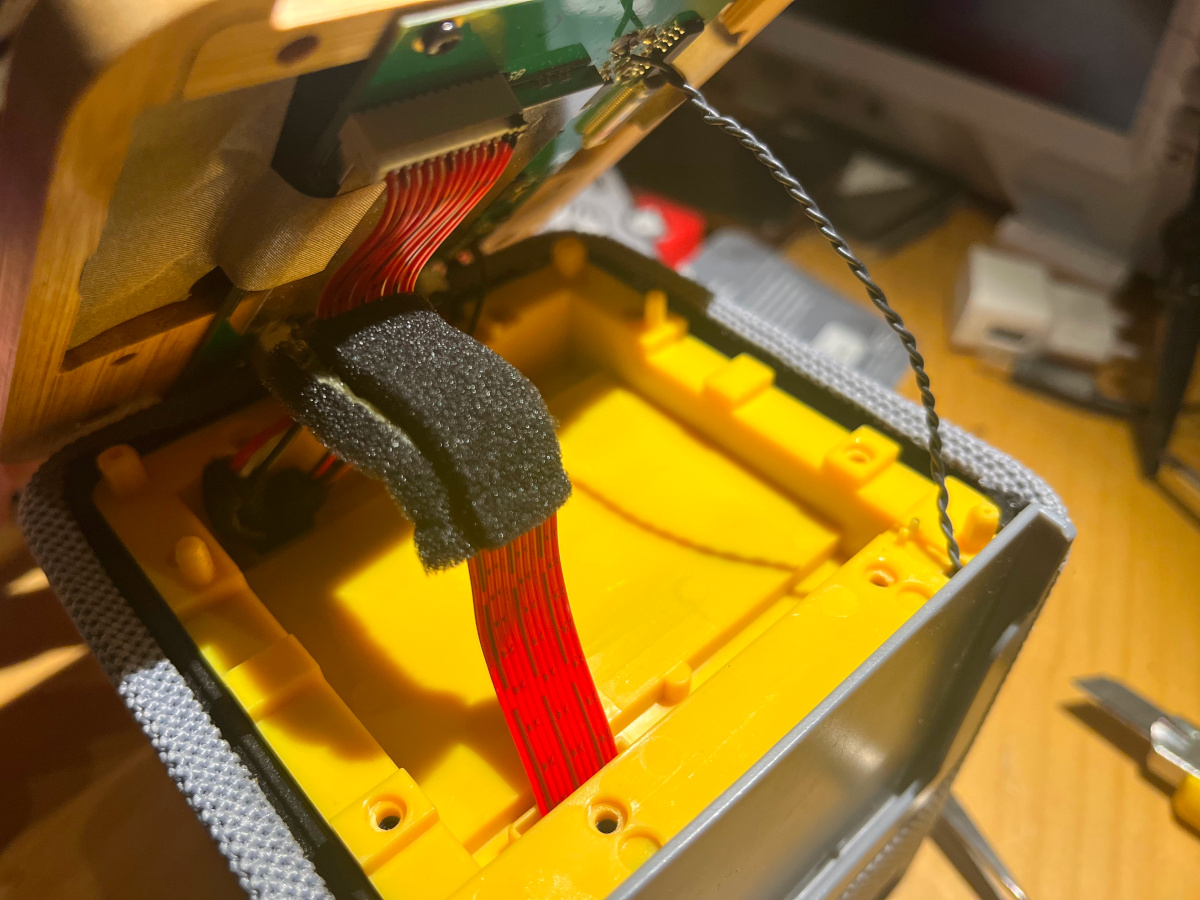
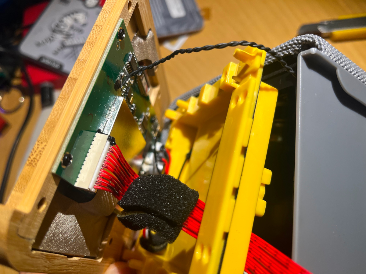
This inlet can be lifted after removing another 8 screws all along the edge. This requires being extremly careful because some of the wires are hard soldered to the PCB and can be teared of very easily. The battery for the newer version of the box is screwed to the bottom of the yellow inlet.
# Differences between versions
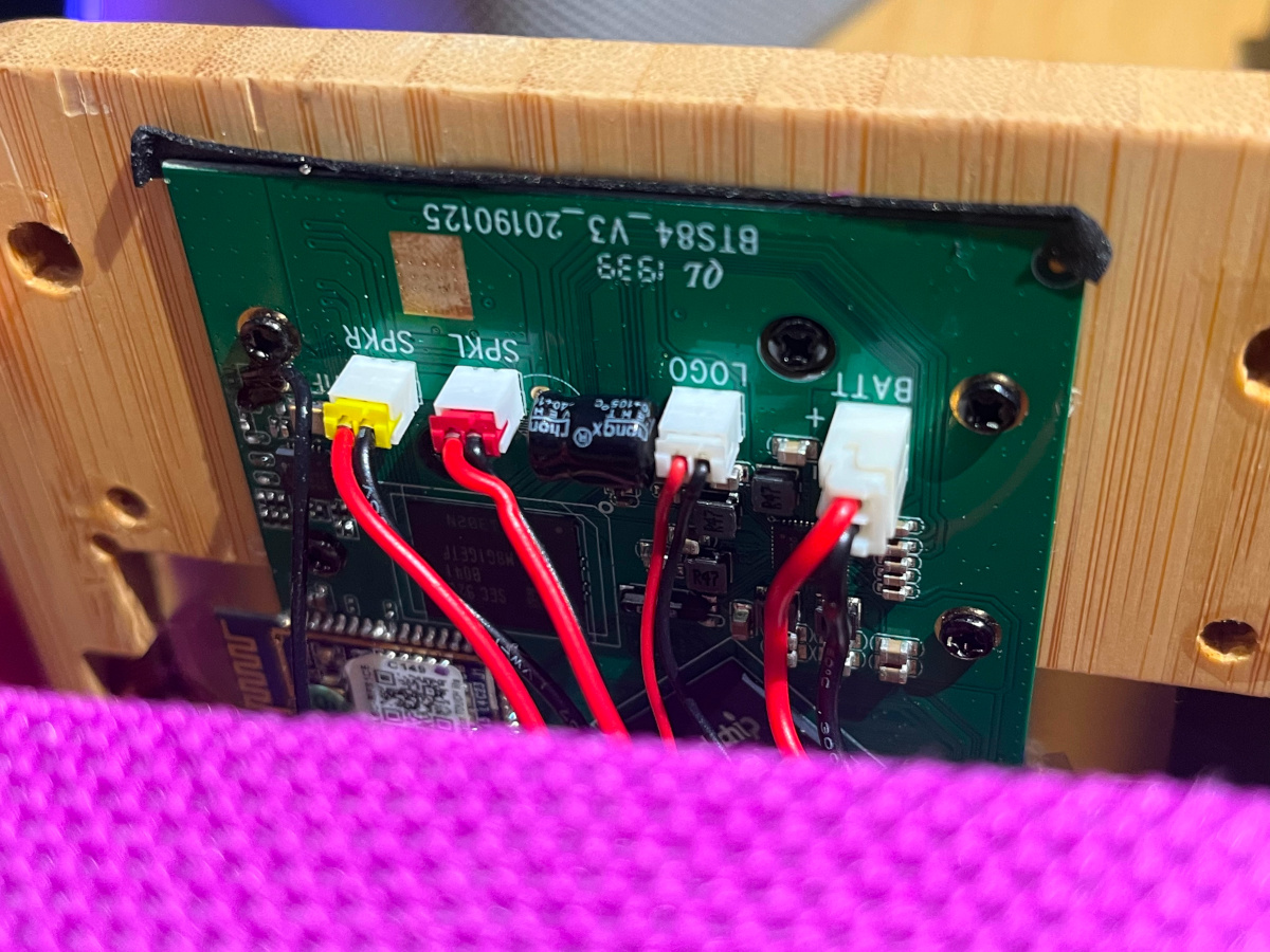
As stated earlier the newer version of the box (as in these pictures) has a 3-pin battery connector. See the most right connector in the following picture:
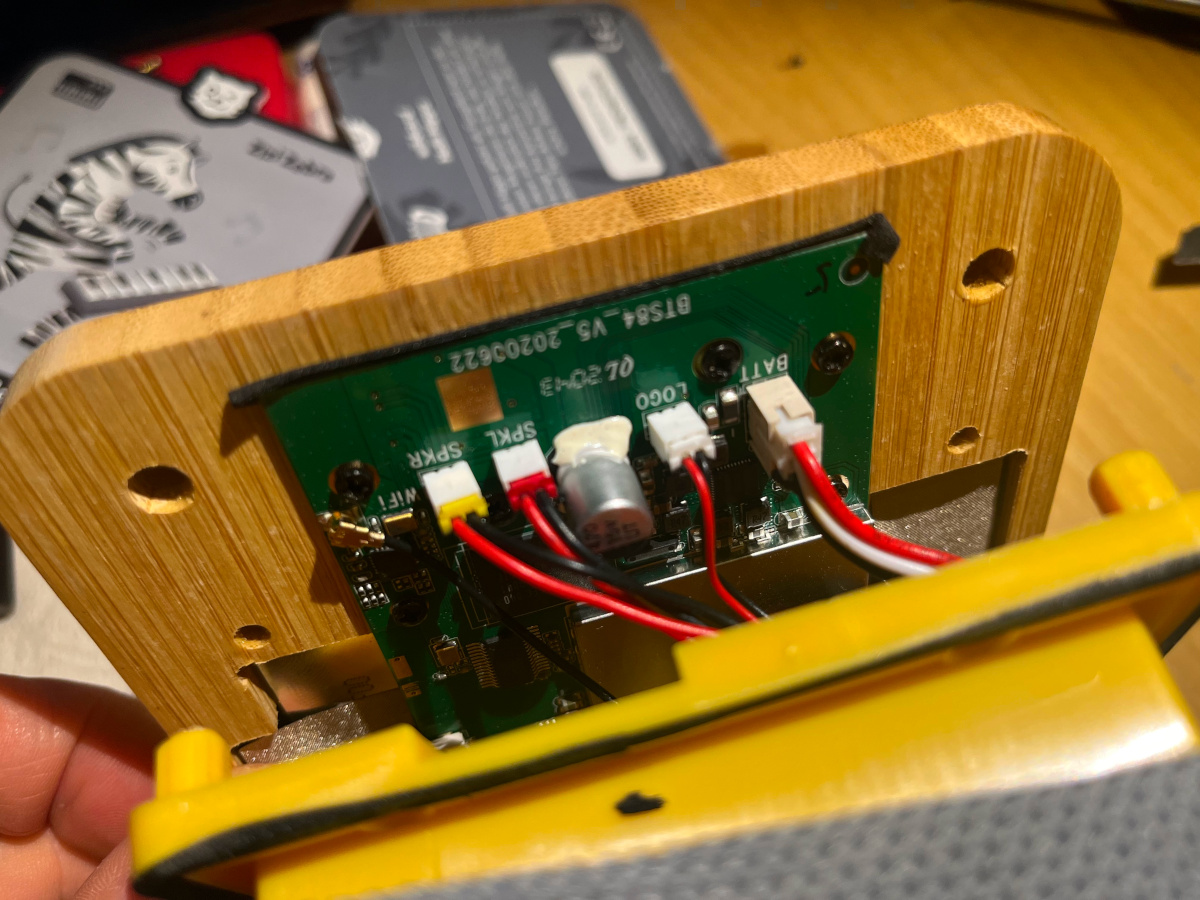
For comparison this is the same part of the main board showing the 2-pin battery connector or another box:
References:
[1] https://x.com/flo0/status/1850478190440915309
[2] https://www.galaxus.de/en/page/how-to-replace-the-touchscreen-on-the-tigerbox-17867