For setting up a DAPNET/POCSAG transmitter there is a very basic solution to control the PTT via a simple resistor/transistor switch on the GPIO port of a Raspberry Pi and feeding the audio from the headphone jack (see [1]). As this solution almost always implied a (small) PCB sitting on the GPIO port and combining audio and PTT lines for a single cable to the transmitter and there are options to have the audio output on some of the GPIO pins instead of the headphone jack why not have a all in one PCB covering this? This would also enable the RPi Zeros to be used for DAPNET as those boards do not have any headphone jack to output audio.
The basic part is to use a device tree overlay which enables the PWM output on some of the CPUs GPIO ports. There are two pairs of GPIO pins to choose from. This leaves room for other applications / pins to be used for other stuff. The DT overlay README shows:
Name:   audremap
Info:   Switches PWM sound output to GPIOs on the 40-pin header
Load:   dtoverlay=audremap,<param>=<val>
Params: swap_lr                 Reverse the channel allocation, which will also
                                swap the audio jack outputs (default off)
        enable_jack             Don't switch off the audio jack output. Does
                                nothing on BCM2711 (default off)
        pins_12_13              Select GPIOs 12 & 13 (default)
        pins_18_19              Select GPIOs 18 & 19
        pins_40_41              Select GPIOs 40 & 41 (not available on CM4, used
                                for other purposes)
        pins_40_45              Select GPIOs 40 & 45 (don't use on BCM2711 - the
                                pins are on different controllers)
So basically a dtoverlay=audremap enables the sound output on GPIO pins. The default is GPIO 12 and 13. On a Raspberry Pi 3B those are routed to pins 32 and 33 of the 40-pin GPIO header. After enabling the audio remap and rebooting pinctrl shows the following output:
$ pinctrl | grep PWM
12: a0    -- | lo // GPIO12 = PWM0
13: a0    -- | lo // GPIO13 = PWM1
Alternatively the GPIOs 18 and 19 can be used if the overlay is enabled with option pins_18_19. Then the PWM/audio is available on pins 12 and 35 of the 40-pin header. pinctrl shows:
$ pinctrl | grep PWM
18: a5    -- | lo // GPIO18 = PWM0
19: a5    -- | lo // GPIO19 = PWM1
40: ip    -- | lo // PWM0_OUT/GPIO40 = input
41: ip    -- | lo // PWM1_OUT/GPIO41 = input
For research reasons here is the output on a Raspberry Pi 1B (the very first version). The GPIOs 12 and 13 are not routed to the (26-pin) GPIO header. So instead GPIOs 18 and 19 might work. But only GPIO 18 is routed to the GPIO pin header on pin 12 (thats why probably 19 is labelled “NC” as are 12 and 13). This needs to be tested.
$ pinctrl | grep PWM
18: a5    -- | lo // GPIO18 = PWM0
19: a5    -- | hi // NC/GPIO19 = PWM1
40: ip    -- | lo // PWM0_OUT/GPIO40 = input
45: ip    -- | lo // PWM1_OUT/GPIO45 = input
This mapping is the same on a Raspberry Pi 4B as well as a Raspberry Pi 0 2W. However, on a Raspberry Pi 5 this does not work. No further debuggung was done here but the way described above simply does not work. For more info on GPIO pin-out see [2].
With this preparation a simple HAT PCB was designed routing the audio output from the GPIO header along with some filtering and a PTT circuit was designed. There are two solder jumpers on the board which allow for selecting the corresponding PTT / audio output pin. The schematic is very simple:
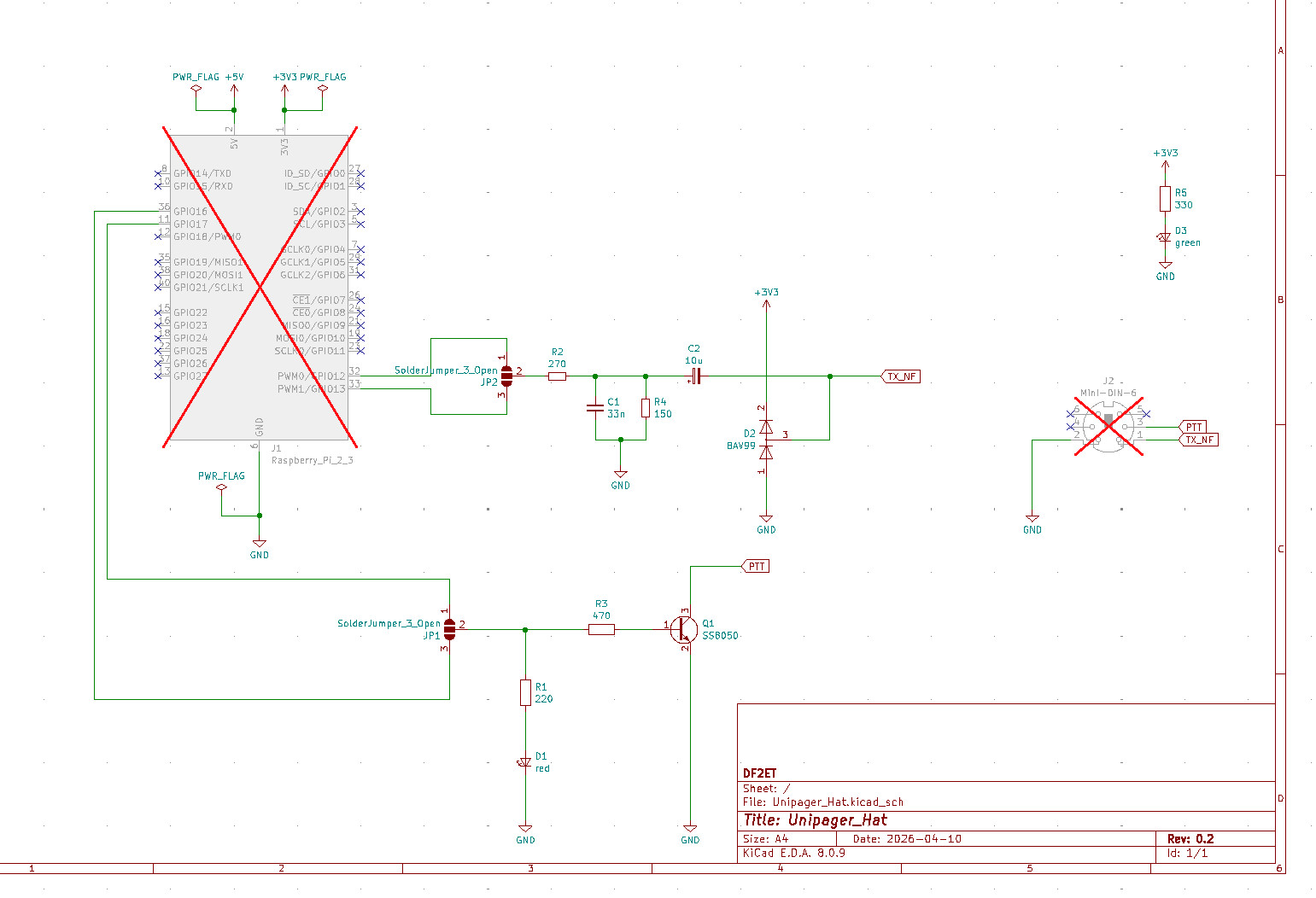
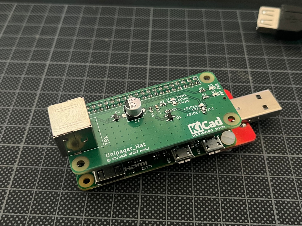
The connector to the radio is a mini DIN socket with the same wiring as used for TNCs and 9k6 ports on radios. So a simple 1:1 cable can connect the transmitter. The PCB was ordered from JCPCB with the SMD parts assembled. Turns out that the first revision only had a minor bug with the audio GPIOs pins being labelled interchanged and the LED resistor for PTT being a little too high in resistance. Other than that the board worked right from the start and is now serving two transmitters in the DAPNET network.
The settings for Unipager are simple. Just set the transmitter type to Audio and use default as device. If needed you can adjust the output volume using alsamixer. The type for PTT is GPIO and just requires the correct GPIO pin to be configured. This should be set to 17 (or 16 depending on the jumper on the board) and the system should be ready to go. The armhf binary for Debian Bullseye on a Raspberry Pi Zero (i.e. the very first version) cannot control GPIO 16 / pin 36 for some reason. In this case GPIO 17 / pin 11 does work with the solder jumper set accordingly.
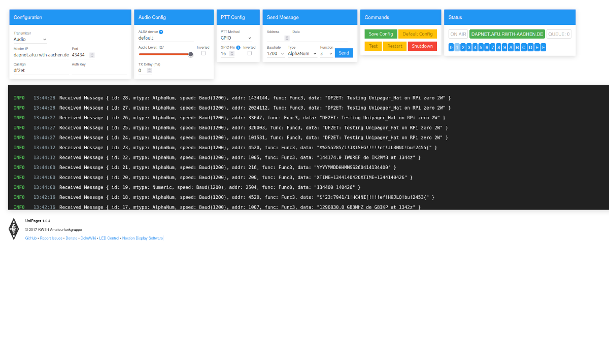
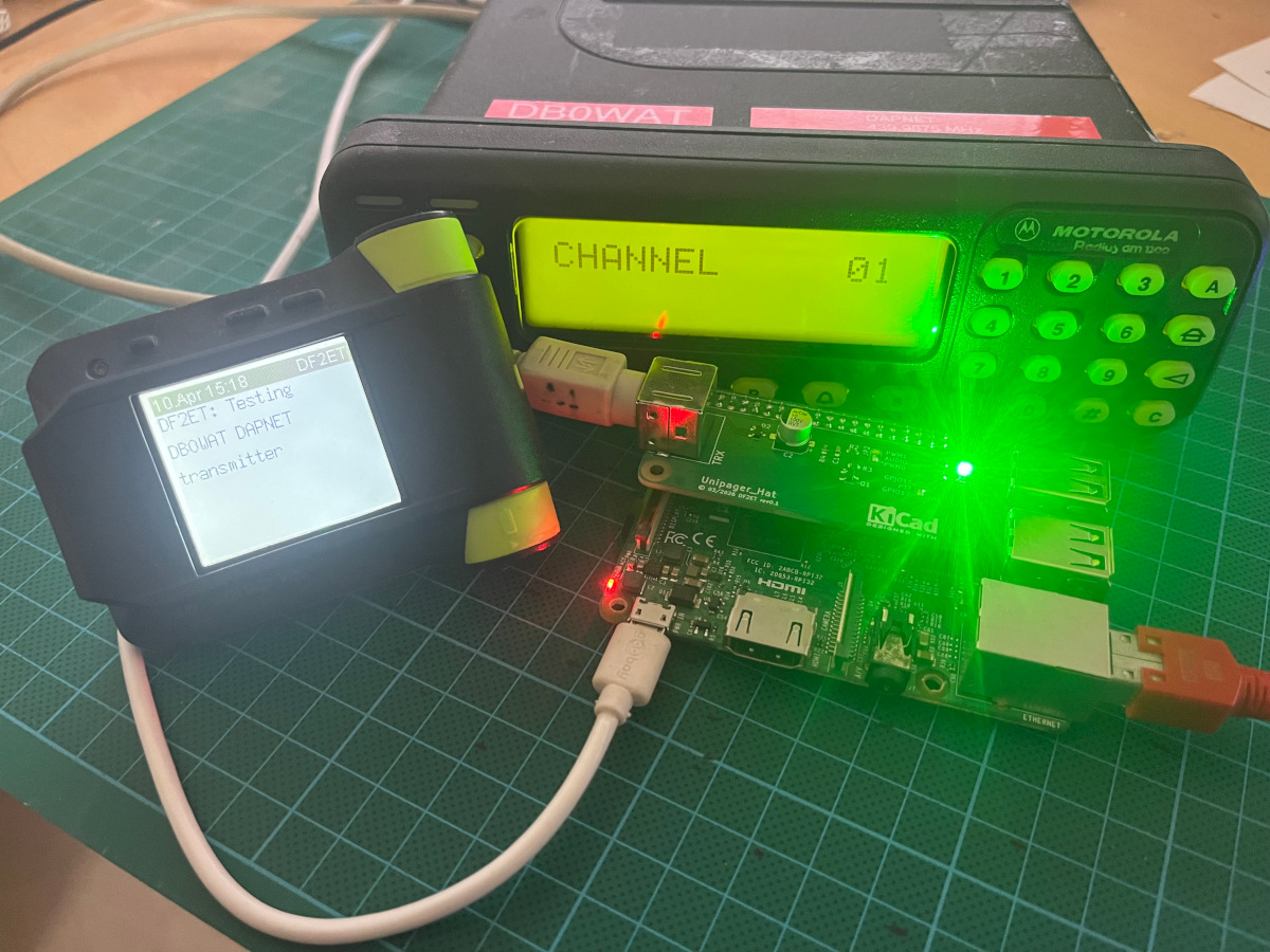
The audio level might need a little adjusment depeding on the type of radio that is used. The very common Motorola GM1200 should work out of the box with input via flat audio on the ACC connector.
References
[1]: https://hampager.de/dokuwiki/doku.php?id=9k6
[2]: https://pinout.xyz/pinout/pwm